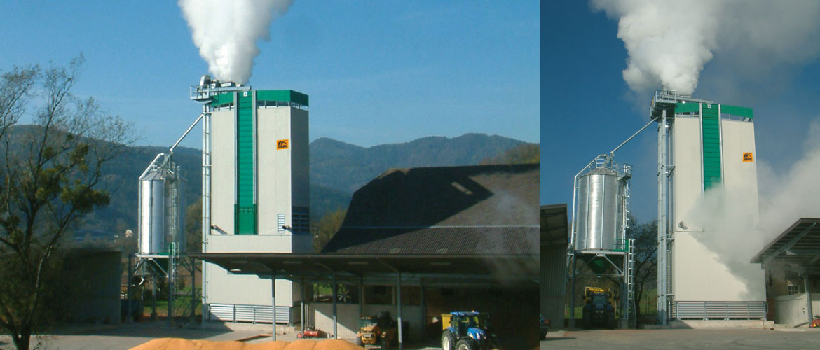
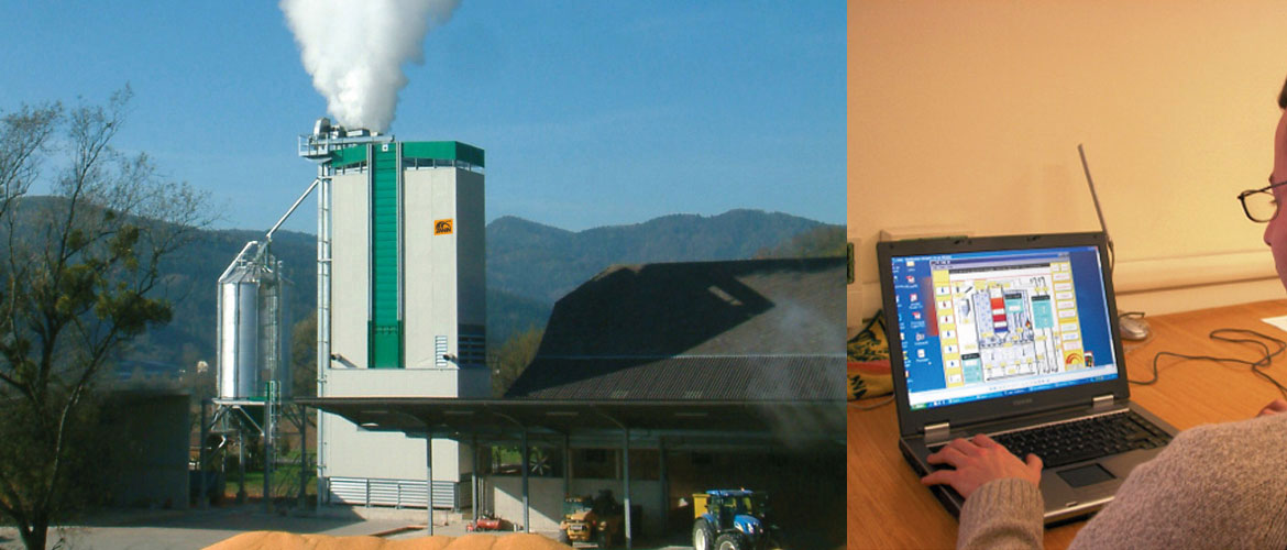
ERCL series Dryer
ENERGY-SAVING WITH INCORPORATED DRY SYSTEM
Caratteristiche
Lower fuel consumption
Less electricity consumption
Less cracking
Higher protein value
Greater specific weight
Higher valid product rate
Excellent preservation in storage
Specifications
Available in various sizes and models with capacities from 396 to 1320 t./24h.
COMPONENTI
Air duct
The panels forming the air chambers are made of: mineral wool sandwich panels,
heated air section and saturated heated air section (prevents the formation of condensation and mulch inside the chamber).
Smooth interior and exterior walls.
Versions: Aluzinc-Galvanized-Precoated in various colours - Aluminium-Stainless steel 304.
Reinforcing uprights and ledges with rung ladders are installed inside the dryer for control and maintenance purposes.
Fans
The depressurised drying system, offering maximum attention to detail, is the most suitable for dust containment. Each dryer is equipped with axial fans with variable pitch blades with different diameters,
exploiting the machine's output and minimising consumption.
Zanin uses technologically advanced brands in the European fan sector to optimise the characteristics of its products.
Hot air generators
The following types of heating units are used for drying:
- direct fired
- indirect fired
- diathermic oil or steam
Possible fuels are:
- Methane gas
- LGP
- Diesel
- Heavy oil, vegetable oil or sub-products
- Biomass
The following types of burners are used:
- pressurised
- air
- special for different types of fuels
Electrical cabinet
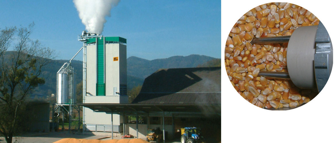
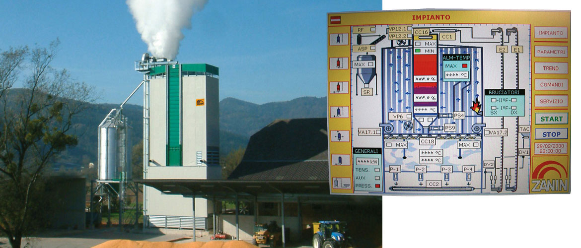
Dryers are equipped with electronic control devices and PLC management. Electronic control system to manage product moisture with contact sensor.
Operating principle
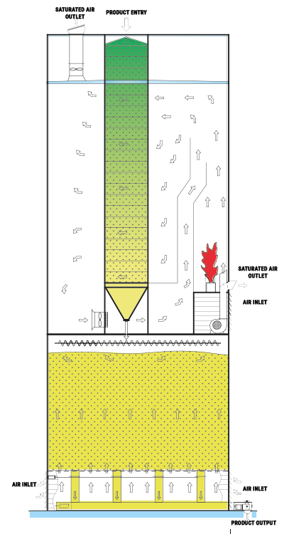
THE DRYING COLUMN is formed by an upper feed hopper and a certain number of modules inside which ducts are buried in the grain.
The grain drops by way of gravity in a zig-zag pattern. The grain then hits a counter-current of warm air.
Split in outfeed, the upper part of the air flow is dispersed in the atmosphere while the lower part is recovered.
The quantity of grain in outfeed is predetermined and regulated by a pneumatic extractor.
The product is then collected in a discharge hopper.
From the discharge hopper, the grain (which is still warm) is sent to the recovery area underneath, and then to the cooling area for slow cooling.
The extraction area is regulated by several pneumatic extractors to ensure maximum possible consistency of the mass product in outfeed.
